Material
Compare candidate materials against strength, manufacturing process and corrosion exposure. A change in material can affect the bearing interface and should be examined with its complete load path.
Wheel Lab
Explore how material choices, simulation, testing and sensing can be connected in a wheel-end development program.
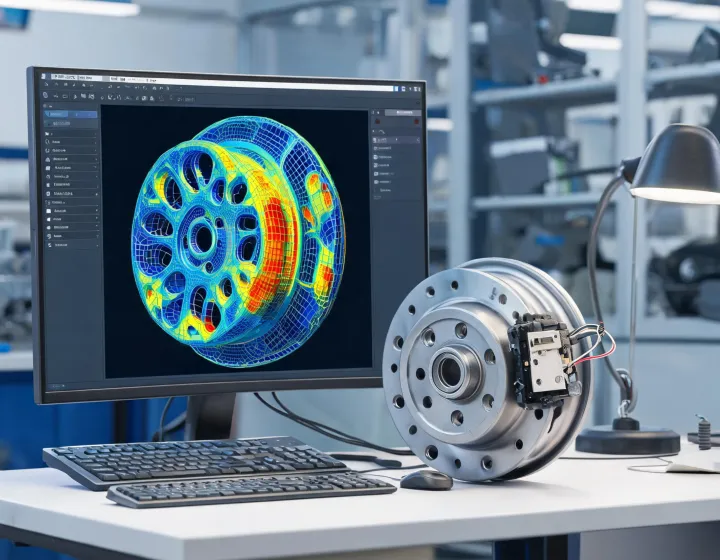
Each panel represents a question to resolve during a program. The details and evidence depend on the product and the agreed operating conditions.
Compare candidate materials against strength, manufacturing process and corrosion exposure. A change in material can affect the bearing interface and should be examined with its complete load path.
Use geometry and stated boundary conditions to explore stresses and deflection. A model is useful when its assumptions are documented and its results are interpreted alongside physical measurements.
Define load, speed, environment, duration and acceptance criteria for a rig evaluation. Results apply to the tested configuration and should not be generalized beyond that scope.
Review ABS encoder placement, signal interface and installation clearances with the vehicle system. Electrical compatibility must be confirmed for the particular application.
Investigate mass opportunities together with stiffness, fatigue and manufacturing constraints. Any claimed reduction requires a baseline and a documented comparison method.
An integrated hub can reduce assembly variation and combine sensor interfaces; a serviceable bearing can preserve component-level repair where the platform permits it. Compare installation procedure, available parts and total service cost before selecting either approach.
Keep drawings, revisions and test records connected so that an engineering change can be assessed against the relevant configuration.
Review the relationship between bearing setting, operating temperature and the load envelope before establishing a validation plan.
Identify exposure scenarios and select a representative test environment for the proposed seal arrangement.
Describe the sensor position, expected signal and mounting tolerances as part of the system interface.
Record platform geometry, load and target market.
Compare concepts and agree the assumptions used in analysis.
Test the selected configuration against defined criteria.
Connect changes and results to the correct revision.
Share the design challenge, available drawings and expected operating envelope.